
Replace your ai-25 with a TFE-731
all you need for a straight-forward conversion
With our replacement module you get a 1000+ hour Honeywell TFE731-3 engine that rolls in on the stock L-39 rails after modification and connects to fuel, throttle and bleed air like an AI-25. Electrical power, engine controls and instrumentation tasks remain.
How is it done?
The following description assumes the reader is an accomplished capable L-39 mechanic with the ability to do aircraft modifications with a high degree of craftsmanship. This write up describes what needs to be accomplished in general terms with the exact implementation being the responsibility of the installer.
There are three general areas that must be addressed when fitting the E2W TFE731 engine installation module (module or 731 used interchangeably ) in the L-39. These are high current DC (HCDC) (Starting/Generating), bleed air and instrumentation. I’ll cover these below in a way meant to inform the installer and not as an absolute step by step description of the only way to do the installation. Where helpful, I will describe the decisions we have made in building the American Albatros which, at its core, has the module installed.
HCDC
Differences
The largest systems difference between the AI-25 installation and the module is the starter/generator functionality. The 731 is an electric start requiring a starter/generator (SG) and a Generator Control Unit or GCU. The HCDC consists of batteries, a master contactor, a starter/generator online contactor, high current wiring to the engine mounted starter/generator, GCU and related wiring. Associated with the HCDC system is the engine start panel as the pilot interface to the starting sequence and related generation functions.
Batteries
Turbine engines require tremendous initial surge battery capacity and thus manufactures make specific “turbine” batteries for these applications. These batteries are expensive on a $ per amp-hour basis, are heavily taxed during their life and tend to need replacing every 24 months (fail capacity check). However, they are compact. On the American Albatros we decided to use four high capacity premium piston aircraft batteries, two series battery sets in parallel. This doubles the available amp-hour capacity (and thus aircraft reserves in case of generation failure) at half the cost of a traditional turbine aircraft battery. By using two sets in parallel, we halve the current draw on each set of batteries to protect them. It also takes up twice the room and doubles the weight. We use the extra weight as part of the needed nose ballast in the L-39 to reduce overall aircraft weight but this requires very long high current conductor runs to the back of the plane. One installation choice would be to place a turbine style battery in the RAT bay (in place of the RAT perhaps) and have very short runs of high current wiring (less cost, work and wire weight). The module weights less than the AI-25 and safir thus overall aircraft weight and weight and balance would not be negatively affected. In short, there are options.
HCDC Installation
No matter where the battery(ies) is/are installed, the components that need be installed are the same. The path is the battery to the master contactor to the 24v DC bus. Off the 24v DC bus you have a starter contactor and a generator online contactor in traditional installations where the start DC bus is different than the ship’s 24 Vdc bus. With the L-39 the two buses are the same and thus we use a single contactor for both start and generator online. The high current wiring goes from the start contactor to the SG and then high current lead(s) from the SG to the chassis or ground. Current transformers are placed just after the start contactor and just before chassis ground which allows the GCU to identify ground faults and isolate the high current lead if necessary (shorting protection). Great care must be taken to properly install and secure the high current conductor(s) from the starter contactor to the SG.
Consideration must be given to where best to introduce the module’s 24 Vdc bus into the existing airframe and how that entry point will work with the ground power isolation requirements. In addition, any ground power considerations must now include the fact that ground power requirements for aircraft starting are MUCH greater with the electric start 731. The American Albatros does not have a ground power option and thus we have not considered these issues in our installations.
Engine Start Panel
Part of the HCDC system is the GCU and related switches and breakers that allow pilot control over the start cycle and generator operation. This is a picture of the American Albatros’ engine control panel

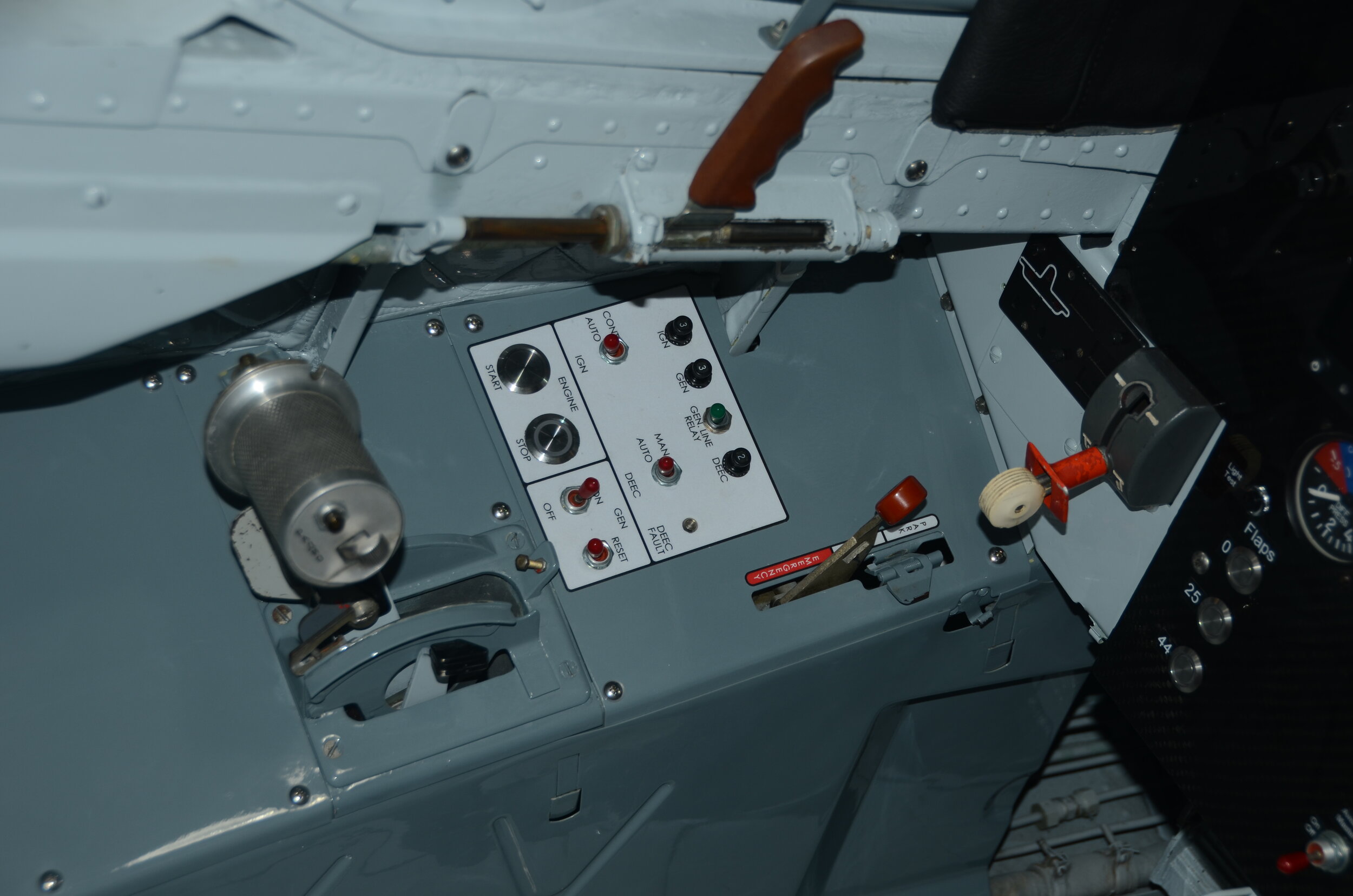
which includes the starter/generator support along with support for the engine’s ignition system and Digital Electronic Engine Control or DEEC. This capability must be replicated in the cockpit during the conversion process. As for the GCU, we mount the unit very near the location of the original L-39 carbon pile generator voltage regulator (removed as no longer needed) to keep the high current PWM shielded signal runs as short as possible.
Bleed Air
Differences
The AI-25 has a single last stage bleed air tap which supplies the ACM (turbo cooler)/cabin pressurization system and the inlet/windscreen anti-ice functions as well as the high volume low pressure regulator that produces regulated air for transferring fuel from the tip tanks to the main tank and for the inverted fuel accumulator (air side). The 731 has a two stage bleed air arrangement where both low pressure LP (at the end of the axial compressor stages) and high pressure HP (exit of the centrifugal compressor) sources are available. The module incorporates a bleed air mixing system mounted on the engine assembly that provides HP bleed air at low power settings transferring to LP bleed at higher power settings. This ensures adequate pressure and temperature in the bleed air to support airframe systems throughout the engine’s operating range.


Implementation
As mentioned above, the bleed air mixing system is engine mounted. The top (12 o’clock) HP tap normally used for inlet nacelle de-ice on certified business jet installations is plumbed around the right side of the motor to an HP shut off valve located at approximately 2:30 on the motor. The HP shut off valve uses HP pressure to shut off the HP feed when LP reaches approximately 20 psi. There is a piston in the shut off valve which senses HP pressure and works to close the HP supply as HP pressure increases with increased engine RPM.
The HP valve is mounted on top of the bleed air mixing manifold which bolts to the LP bleed port at the 3 o’clock position on the right side of the 731. A one way flapper valve is captured between the mixing manifold and the 731 motor to prevent HP bleed air from bleeding back into the LP port when he HP supply valve is open. The resultant mixed HP/LP bleed air exits the bottom of the mixing manifold and makes a 90 degree turn towards the front of the plane which completes the engine mounted portion of the bleed air system. Expansion bellows are used throughout to decouple different segments of the system and allow for thermal expansion.
The airframe side of the bleed air plumbing consists of a connection pipe from the engine to stock AI-25 bleed air shut off butterfly type valve (supplied by the installer presumably from the previously installed AI-25). An adaptor attaches the AI-25 bleed air shut off valve to the ACM mass flow regulator in the upper right hand portion of the engine bay. Note the American Albatros solution removes the stock L-39 air cleaner as no such filter exists in business jet installations. We have done installations that retain the L-39 bleed air filter and have an adaptor that will mount the original AI-25 bleed air shut off valve directly to the air cleaner. This necessitated moving the air cleaner bracket one rivet outboard so that filter can clear the oil tank. The installer would be responsible for bracketing to support the valve’s new installation position as well as changing the forward running bleed air piping on the module to properly align with the altered airframe arrangement should they want to retain the air filter. Note, that by using the original AI-25 bleed air shut off valve, all the original L-39 bleed air cockpit controls are retained.
A pressure and temperature tap are provided on the airframe bleed air piping before the ACM (turbo cooler) shut off valve to allow pilot monitoring of bleed air temperature and pressure.
A 1” tap is provided on the airframe bleed air piping to attach piping and an anti-ice bleed air shut off valve. The outlet of the anti-ice bleed air shut off valve is then plumbed into the original anti-ice bleed air supply port on the engine to RAT bay firewall. The anti-ice bleed air shut off valve is a fail open unit typically found on the Hawker or WestWind and is supplied with the module installation package.


Instrumentation
Differences
The differences between the AI-25 and 731 instrumentation/pilot interface are the starter/generator/DEEC elements described in the HCDC section and overall engine instrumentation. Like the AI-25, the 731 is a twin spool motor requiring pilot display of both N1 and N2. The 731 has an integrated fuel flow turbine as well as oil pressure sensor, oil temperature sensor, low oil pressure switch, low fuel pressure switch and, in some installations, fuel filter bypass switch and oil pressure bypass switch. Some of these functions mirror those on the AI-25 and some are in addition to the AI-25. In all instances (but perhaps the low fuel pressure switch) provisions must be made for engine instrumentation.
There is tremendous freedom in approach to this task. On the American Albatros we literally removed all the wiring in the cockpit and fuselage apart from some switch wiring in the wing and nose box. In its place we installed a complete bespoke laser marked Tefzel wiring harness and full Garmin avionics suite. The far other end of the spectrum is to procure N1/N2 and ITT gages from something like a Hawker and install those along with an oil pressure and temperature gauge. A solution that is between the two would be to install something like a Garmin GDU460 or EI MVP-50 engine monitor display.
To support instrumentation installation, the fuel flow turbine sensor is replaced with one we have had produced that provides an open collector output similar to standard GA fuel flow meters like the “EI Cube”. We also provide an N1/N2 signal conditioning box that converts the high frequency (roughly 10 KHz) zero crossing sine wave output of the N1/N2 monopole sensors to a reduced frequency logic level square wave compatible with the Garmin G3X suite and other instrumentation systems.
Wiring
We source motors from many different airframes including WestWind, Hawker, Citation and Sabre. They all have different engine sensor wiring harnesses and thus we normally remove the original sensor harness and build our own replacement. This keeps the American Albatros installations consistent and permits us to easily swap motors in and out.
DEEC
The engine computer or DEEC can be installed in the RAT or engine bay. The module is provided with an N1 DEEC, mounting bracket and WestWind DEEC airframe harness. This harness has three primary connections. It attaches to the DEEC, the DEEC engine harness and it has a connector for DEEC to airframe which is where the installer access signals like N1/N2, DEEC Manual Mode Light and the engine 50% signals used to tell the GCU to terminate the electric start cycle as the engine is far enough along to accelerate to idle without help from the starter.
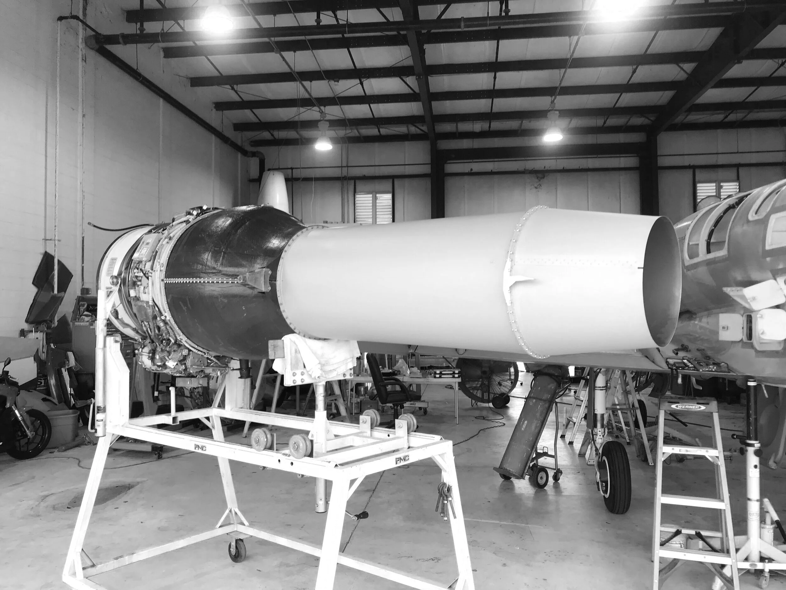
Module Installation
The 731 module assembly is designed to roll into the original AI-25 location using the original engine mounting points in the same way as the AI-25 with a few notable changes. First, the 731 is a higher bypass engine with a larger diameter fan thus the inlet is larger. The original L-39 motor air inlet tube is remove. The screw on seal ring mounted to the engine to RAT bay firewall is removed. The lip on the firewall where the nut plates that were used to secure the above mentioned sealing ring is cut off. Once this is done, the module with air inlet tube attached then rolls into the engine bay and clamps in place.
Once clamped in place, the hight of the exhaust must be adjusted so the pipe is centered in the tail. Unlike the AI-25, the module has no “gator teeth” on the rear motor mounts or eccentric shafts to permit up and down adjustment. Instead, the steel sliders are fabricated with offset mounting holes to permit up and down adjustment of the left and right rear motor mounts. The installer puts the sliders in the “zero” position, rolls the tail on to measure up/down error then pulls the tail off to adjust the sliders accordingly.
Lastly, the module is provided with two un-drilled rear exhaust mounts. Once the exhaust tube is properly centered in the tail, the rear exhaust hangers are installed in the rear hanger spring mounts, offered up to the exhaust tube then clamped in the correct location. The tail is then removed and the mounting holes transferred from the exhaust to the hangers and the hangers are permanently installed.

our hangars are open to visits and demo flights.
DO COME AND FLY!